1.1. Configure command code docking
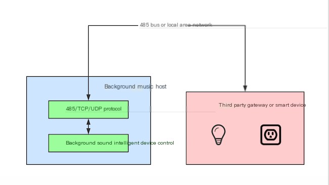
Configure command code connection, that is, through adding devices or scenes and configuring corresponding control codes on the related interface of the small host to achieve home control
1.2. Interactive Chart
1.3. Video operation view
1.4. Turn on smart home mode
The current document demonstrates the model P5, and the operation steps for other models are also similar
Click sequentially, Settings -> General Settings -> Smart Home Settings, open the Smart Home mode
1.5. Enter 485 host management
Click sequentially, Top Drop-down - Settings - RS485 - 485 Host Configuration
Enter the administrator password "admin"


1.6. Configure interface type
Supports three communication types, 485, UDP, and TCP (Little can act as a client, UDP/TCP debugging tools or gateways act as servers; Little client fills in the IP address of the debugging tool server for network connection, and the port is defined by yourself)


1.7. Add device
Click on "Floor, Room, Equipment Configuration" in the image below

1.8. Add floors, rooms
Click the Add Floor button in the image below


Click on a room, the interface is as shown below, click the plus icon to add a device

For example, add a curtain, click the middle of the curtain image, pop up the interface, edit the command code


The figure below allows direct input of control codes and response codes. It can also use the learning function, which is similar to the learning principle of infrared remote controls, and can receive control commands from the 458 bus or UDP broadcasts.
Control code: It refers to the code sent out when Xiao Ke clicks on a function or controls a function (such as turning on a switch).
Response Code: The response code indicates the code for a certain status of the device, such as a light. First, add a light device to the small K host and set the 485 control code and response code. When the light is turned on on the small K, the small K host will issue the control code. The 485 bus receives the control code, responds with a code that matches the set response code, and after the small K host receives it, the UI status of the light on the page will change to on.
Note: Do not add spaces when setting the response code, and also remove spaces when sending the response code
Click, learn "Control Code", if a control code is received, it will be automatically filled into the control code input box
Click, learn about "response codes." If a control code is received, it will be automatically filled into the control code input box
Click, learn about "Control and Response Codes," if two control codes are received, they will be automatically filled into the control code and response code input boxes
 Add 3 commands for curtains, as shown in the figure below, after completion, click Save to return

Note: When the 485 coding control device is activated, the response code is delayed, greater than 10ms
1.9. Main interface displays added devices
Return to the main background music interface, swipe to the left screen

1.10. Add scene
As shown in the figure, click the scene configuration

By default, no scenes are present. Click to add, and a new scene will be created. The scene name supports only Chinese characters and numbers


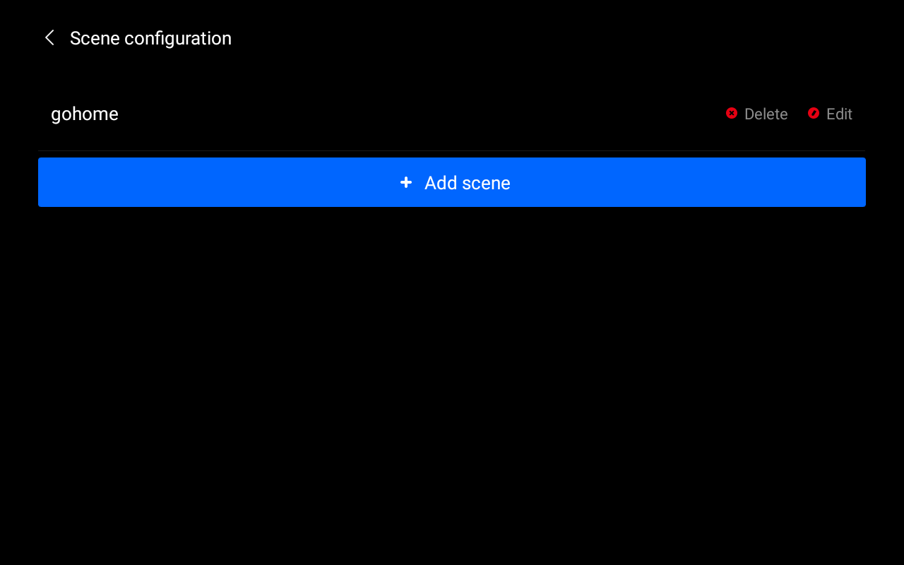
Click the scene to enter the execution instruction interface for adding a scene.
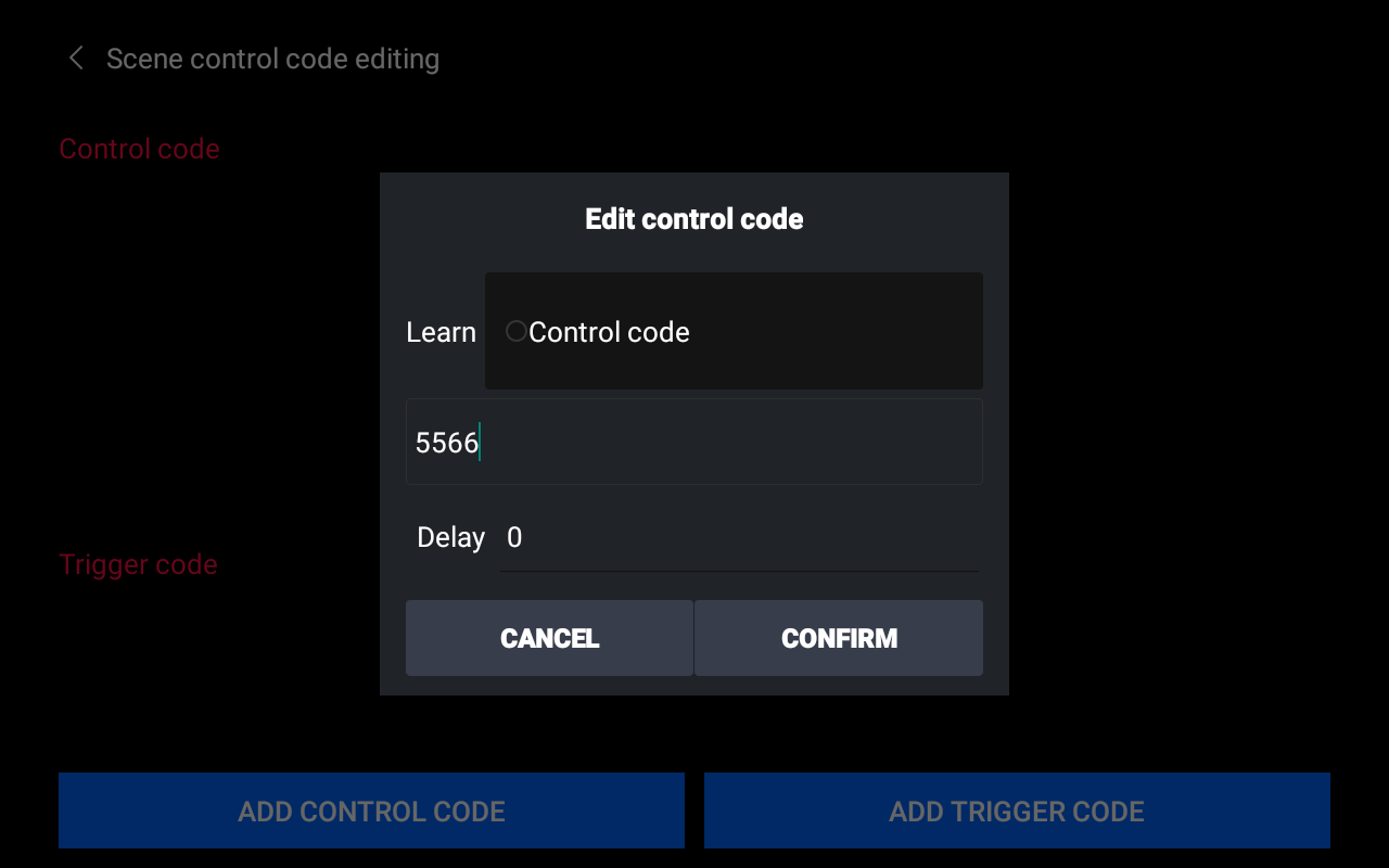
Edit control codes, as shown in the figure, you can directly input control codes. You can also use the learning function, which is similar to the learning principle of infrared remote control, and can receive control commands on the 458 bus, or in UDP, TCP network connections. Click, learn "control code", if a control code is received, it will be automatically filled into the control code input box.
Delay refers to the delayed transmission of command codes, with the unit being milliseconds. If there is no need for delay, it is default to 0.
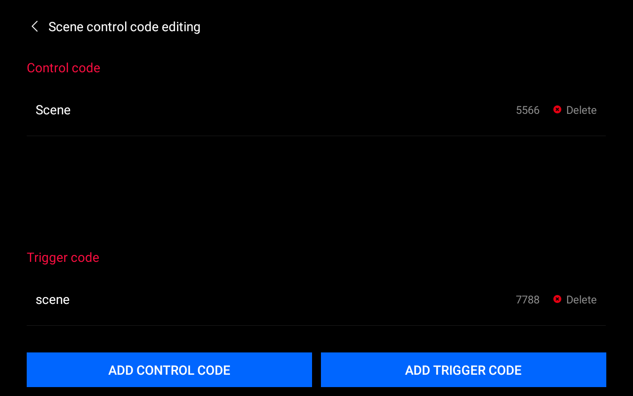
The function of the trigger code: When the Xiao Ke host receives a trigger code via 485, it will execute the scene corresponding to the trigger code. For example, if the added scene includes setting prompts and scene music, after receiving the trigger code, the host will execute the prompt announcement of the scene and play the scene music playlist.
After adding the instructions, as shown in the figure below:
1.11. Main interface view added scenes
Return to the main background music interface, swipe to the right screen
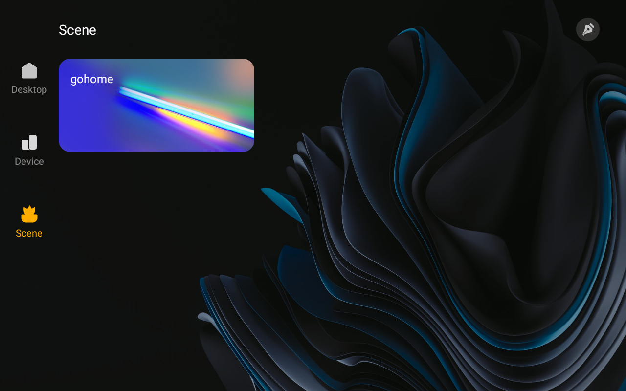
1.12. Implement computer editing instruction code
1. Follow the above steps to enter the interface configuration interface and perform basic protocol configuration (such as: transmission method, protocol type, etc.)
2. Add equipment and scenes according to actual requirements, and you can fill in any placeholder arbitrarily when editing instruction codes.
3. Go back to the following interface, click the export configuration button, and export the configuration file of the newly added devices and scenes to the /sdcard/host_config.ini path.

4. Connect the small host to the computer, find the configuration file just exported, open and edit it, replace the previously randomly written instruction codes with actual control codes, keeping the rest unchanged, save and close. You can copy the edited configuration file to the computer side for backup, so that next time you can directly copy the file to the /sdcard directory of the small host for use.
Note: Do not modify the host_config.ini file name.
Download the host_config.ini file example: Click to download (if prompted to block, this type of file may damage your device, click the file for more actions, and select Keep).
5. Assuming the instructions in the /sdcard/host_config.ini file are correct, enter the interface shown in the image, click the import configuration button to import the host_config.ini file for use.
6. Up to this point, the devices, scenes, and their instruction codes have been successfully added, and users can enter the relevant interface to view them.